This page must be viewed with IE4 or above, and with Active Scripting enabled.
SERIES 24 CSR
Electroswitch 
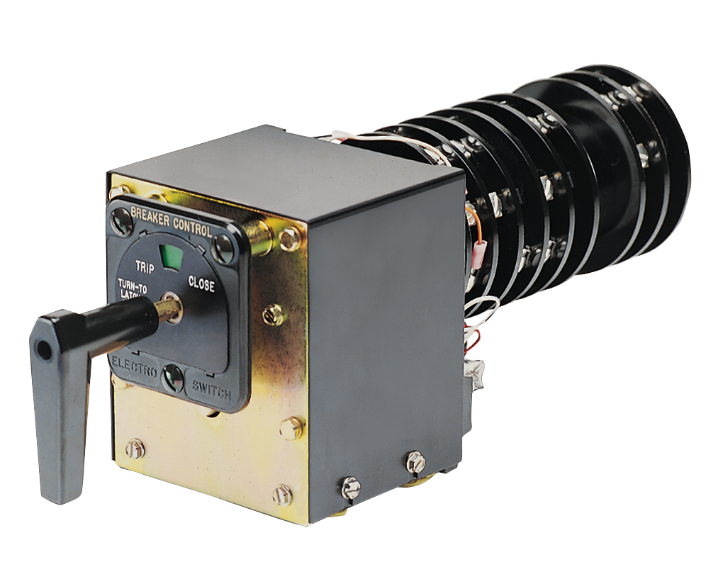
Control Switch Relays (CSR) combine the function of a control switch with a
remote controlled solenoid allowing one device to do both the manual and supervisory control
function in the control of power circuit breakers. They eliminate the need to redesign substa-
tions for redundant separate relays when manual substations convert to supervisory control.
CSRs provide manual or electric control switch operation by supervisory control. The CSR
looks, acts, and feels identical to a control switch.
Note: The Series 24 CSR Class 1E utility products comply with the following Nuclear
Standards: ANSI/IEEE C37.90, ANSI/IEEE C37.90.01, ANSI/IEEE C37.98, ANSI/IEEE
C37.105, ANSI/IEEE 323, ANSI/IEEE 344, ANSI/ASME NQA -1.
Series 24 Control Switch Relays
HIGH QUALITY
Designed and manufactured to the highest standards
in the industry
Qualified to UL, CSA, ANSI/IEEE 37.90 and 37.90 .1
VERSATILITY
Replaces a manual breaker switch, interposing relays, and
associated wiring
Direct retrofit to existing manual breaker control switch
Electric or manual operation
Three circuits to satisfy different industry applications
Multiple voltages: 48VDC, 125VDC, standard, others available
All standard Series 24 circuit breaker control switch contacting
(see page 17) available
Available with custom contacting (consult factory)
SAFETY
Target flag agreement (regardless of manual or electric trip)
Available with SCADA disable for operator safety during service
1E Nuclear qualified
AVAILABILITY
Virtually all Universal Circuits in standard voltages of the Series
24 CSRs are available from stock for quick delivery. See pg.13
(Switch Section) for Series 24 Universal Circuits.
SERVICE
The Electroswitch team of Customer Service and Applications
Professionals stand behind every Electroswitch product. Let us
put over 50 years of know-how to work for you!
Basic Circuit Operation
The control of the CSR Control Switch Relay for electric operation requires no special wiring. It
only requires two contacts (S1 and S2) to command the CSR to either the TRIP or CLOSE
position. Low level contacts (rated 1 ampere) may be used since S1 and S2 do not control
the rotary drive solenoid directly.
The standard station control bus voltage is used on all three circuits. The device, when shown
in the following figures is in the vertical NORMAL position. The CSR coil form shown on the
figures represents the rotary solenoid that drives the CSR. Its operation is further described
later. LS1 is a linear solenoid within the device that changes the sense of direction of the CSR
from left (TRIP) to right (CLOSE). The contacts shown as CSR are contacts within the device.
Other components are shown by conventional designations.
Mechanical Target
When the CSR Switch handle is turned, a mechanical target contained in the nameplate is
turned as well (GREEN for TRIP, RED for CLOSE). The target remains latched when the handle
returns to normal position and always shows the last active position.