|

|
|
|
|
|
|
|
|

|
|

|
|
|---|---|---|---|---|---|---|---|---|---|---|---|---|
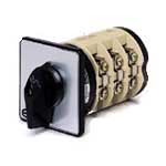
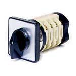
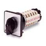
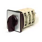
| KW100 Cam Switch | KW12 Cam Switch | KW16 Cam Switch | KW20 Cam Switch | KW200 Cam Switch | KW25 Cam Switch | KW32 Cam Switch | KW40 Cam Switch | KW400 Cam Switch | KW600 Cam Switch | KW63 Cam Switch | KW800 Cam Switch | |
| Mechanical Specifications | ||||||||||||
| Sections | 1-12 | 1-12 | 1-12 | 1-12 | 1-12 | 1-12 | 1-12 | 1-12 | 2-12 | 1-12 | 1-12 | 1-12 |
| Poles | 1-24 | 1-24 | 1-24 | 1-24 | 1-24 | 1-24 | 1-24 | 1-24 | 1-12 | 1-24 | ||
| Positions | 2-12 | 2-12 | 2-12 | 2-12 | 2-12 | 2-12 | 2-12 | 2-12 | 2-12 | 2-12 | 2-12 | 2-12 |
| Detent angle | 30°, 45°, 60°, 90° | 30°, 45°, 60°, 90° | 30°, 45°, 60°, 90° | 30°, 45°, 60°, 90° | 30°, 45°, 60°, 90° | 30°, 45°, 60°, 90° | 30°, 45°, 60°, 90° | 30°, 45°, 60°, 90° | 30°, 45°, 60°, 90° | 30°, 45°, 60°, 90° | 30°, 45°, 60°, 90° | 30°, 45°, 60°, 90° |
| Electrical ratings | ||||||||||||
| Continuous rating | 125A-600VAC | 20A-240VAC | 25A-600VAC | 25A-240VAC | 200A-600VAC | 32A-600VAC | 40A-600VAC | 63A-600VAC | 400A-600VAC | 600A-600VAC | 80A-600VAC | 800A-600VAC |
| Interrupting current120VAC240VAC600VAC24VDC | 100A100A100A100A | 12A12AN/A12A | 16A16A16A16A | 20A20AN/A20A | 200A200A200A200A | 25A25A25A25A | 32A32A32A32A | 40A40A40A40A | 200A200A200A200A | N/AN/AN/AN/A | 63A63A63A63A | N/AN/AN/AN/A |
| Max. breaking ability | ||||||||||||
| Max. making ability | ||||||||||||
| Momentary current1 second | 3000A | 275A | 550A | 407A | 4400A | 690A | 725A | 914A | 4400A | N/A | 2500A | N/A |
| Overload current240VAC600VAC | 480A312A | 40.8N/A | N/A91.2A | 91.2AN/A | 924A372A | 132A102A | 168A132A | 252A168A | 924A372A | N/AN/A | 324A252A | N/AN/A |
| Dielectric strength | 2200Vrms | 1500Vrms | 2200Vrms | 1500Vrms | 2200Vrms | 2200Vrms | 2200Vrms | 2200Vrms | 2200Vrms | 2200Vrms | 2200Vrms | 2200Vrms |
| Insulation resistance | 100 megaohms | 100 megaohms | 100 megaohms | 100 megaohms | 100 megaohms | 100 megaohms | 100 megaohms | 100 megaohms | 100 megaohms | 100 megaohms | 100 megaohms | 100 megaohms |
| Contact resistance | 5 milliohms | 30 milliohms | 30 milliohms | 30 milliohms | 5 milliohms | 30 milliohms | 30 milliohms | 10 miliohms | 5 milliohms | 5 milliohms | 10 miliohms | 5 milliohms |
| Horsepower Ratings220/240VAC440/480VAC550/600VAC | 30HP50HP502HP | 2HPN/AN/A | 5HPN/AN/A | 5HPN/AN/A | 60HP75HP60HP | 7.5HPN/AN/A | 10HPN/AN/A | 15HP25HP25HP | N/AN/AN/A | N/AN/AN/A | 20HP40HP40HP | N/AN/AN/A |
| Other | ||||||||||||
| Switch mountingsSingle Hole2-Hole4-holeWaterproof MountBase-MountDoor-Mount | N/AYesYesYesYesYes | YesYesYesYesYesYes | YesYesYesYesYesYes | YesYesYesYesYesYes | N/AN/AYesN/AYesYes | YesYesN/AYesYesYes | YesYesYesYesYesYes | YesYesYesYesYesYes | N/AN/AYesN/AYesYes | N/AN/AYesN/AYesYes | N/AYesYesYesYesYes | N/AN/AYesN/AYesYes |
| Locking featuresKey-InterlockPadlockable | YesYes | YesYes | YesYes | YesYes | YesYes | YesYes | YesYes | YesYes | YesYes | YesYes | YesYes | YesYes |
| Optional featuresGanged Gear OperatedSpring ReturnKey-Operated | YesN/AN/A | YesYesYes | YesYesYes | YesYesYes | YesN/AN/A | YesYesYes | YesYesYes | N/AYesYes | YesN/AN/A | YesN/AN/A | YesN/AN/A | YesN/AN/A |
| ApprovalsUL RecognizedCSA Certified | YesYes | YesYes | YesYes | YesYes | YesYes | YesYes | YesYes | YesYes | N/AN/A | N/AN/A | YesYes | N/AN/A |
| Display Output | ||||||||||||
| Display Range (Indication) | ||||||||||||
| Meter Power Supply (Aux) | ||||||||||||
| Output Options | ||||||||||||
| Voltage to Measure (Input) |